
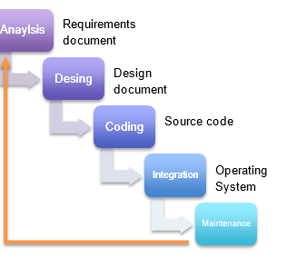
Requirements document
- Analysis: User needs → specifications
- Design: Decomposition into elements that can be developed separately → specifications of each element
- Coding: Programming of each element separately (+ isolated tests)
- Integration: The elements are put together and the complete system is tested
- Maintenance: Occasional changes (errors or improvements).
Prototypes
Rapid prototypes
- Just to gain experience
- The code does not reject
- They are used for the design analysis phases
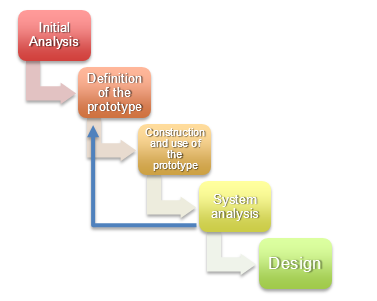
Evolutionary prototypes
- The code is rejected
- Cyclic process of cascade model
- In each round the prototype is improved until reaching a complete system.
Software Specification
System model concept
- The model specifies WHAT the system does without specifying HOW it does it
- Different techniques can be used
- Decomposition in subsystems
- Modification of an existing model
- Domain analysis → study environment, terminology, similar systems.
Requirements analysis
- Objective → obtain the software specifications (build the model)
- Phases
- Study of the system in context: SW system is part of a complex system (SW + HW + mechanics + …..) → study of all other systems + study of the domain
- Identification of needs: interaction with the client → real needs
- Establishment of the system model
- Hierarchical development → division into subsystems + development of each subsystem
- Ends with a requirements specification document
Different possible notations for the specification
- Natural language → for very simple systems or as a complement to others
- Data flow diagrams (DFD) → model the processing of data in the system
- State transition diagrams (DTE) → model system dynamics
- Data dictionary → model the data
Software Design
Design
- Tell how the system will do what it has to do.
- Ends with an architectural design document and a detailed design document.
Phases
- Architectural design
- Structure and organization of the system.
- Division into subsystems or modules + interfaces between them.
- Detailed design → development of each module
- New modules appear, others are grouped or disappear.
- Define the structure of each module, with its data and associated services.
- Design the algorithms for the development of each module → it is detailed in pseudocode without reaching a very detailed level (it would be almost coding).
- Data design → design of the databases associated with the system (if necessary)
Structure diagrams
- It is one of the many tools for design
- Proposed by E. Yourdon as a tool for structured design
- Describe the hierarchy of modules and sub-modules (architectural design)
- The Yourdon module concept fits into what is a C function
Characteristics that a Module Must Fulfill
Coupling (it must be weak) → it is the interrelation that it has with other modules
- (Very Strong) By content → access to local data and code (between modules).
- (Strong) Common → data area common to several modules.
- (Medium) Control → the modules are passed control signals.
- (Weak) By reference → the modules are passed data by reference (eg: C struct).
- (Very Weak) By value → passing data from one module to another (only the ones you need).
Cohesion (must be medium / high) → group related elements in a module
- (Very Low) casual → no relationship (eg: I take a program of 1000 lines of code, I break it into blocks of 100 lines and I make a module with each block).
- (Low) Logic → the module contains operations whose execution depends on a parameter (eg: a Calculation function (operation, data) that can make sums or products).
- (Medium-Low) temporary → the module contains operations that are executed at the same time (eg: system initialization routines).
- (Media) communication → the module performs different operations that run in “parallel” and that they all operate on the same data set.
- (Medium-High) sequential → the module performs different operations that are carried out sequentially on the data, so that the output data of an operation is input data for the next.
- (High) functional → the module performs only one function.
Comprehensibility → simple and understandable functioning (for those who have not designed it).
Adaptability (very difficult) → possibility to change it easily.
Design Document (In the case of modular design)
1. Introduction → overview of the document
- 1.1. objective
- 1.2. Ambit
- 1.3. Definitions, acronyms and abbreviations
- 1.4. References
2. Overview of the system → overview of the requirements + reference to the requirements specification document.
3. System context → connections with other systems.
- 3.n. Definition of external interface,
4. System design → description of the upper level of design (architectural design)
- 4.1. High-level design methodology → description of the methodology used
- 4.2. Decomposition of the system → system components (modules) and the relationship between them.
5. Design of the components → design of each module.
- 5.n.0. Identifier of the component.
- 5.n.1. Type → module.
- 5.n.2. Objective → justification of the need to exist.
- 5.n.3. Function → what does it do?
- 5.n.4. Subordinates → components (modules) what do you use.
- 5.n.5. Dependencies → components (modules) for which it is used.
- 5.n.6. Interfaces → rules of interaction with other elements (modules).
- 5.n.7. Resources.
- 5.n.8. References.
- 5.n.9. Process → algorithms (defined with pseudocode).
- N 5.n.10. Data → internal data used by the component (module).
6. Feasibility and estimated resources → to carry out the system.
7. Matrix requirements / components.
Development Proposal for Small Systems
Specification (Analysis)
- Very briefly say what the system does without saying how.
- In natural language or structured natural language,
- No software specification document → included in the design document
Design
- Architectural design
- Division into modules and the interfaces between them.
- Reflected in a structure diagram.
- Detailed design
- Design of each of the modules.
- Specified as pseudocode (best) or flowchart.
- Is reflected in the design document.
- Coding.
- Tests.
Design document
- Brief introduction and overview of the system.
- Detailed development of system design and components.